 Figure 1
Here is the circuit diagram:
Figure 1
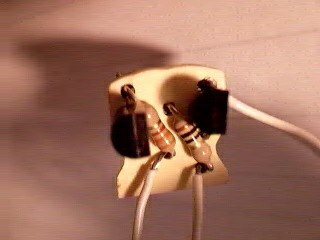
Designing a PCB for this circuit that would fit in the cavity behind the Rayovac's original PCB was a challenge. I needed a board that would fit in the small space behind the lamp's original circuit board. Below is a drawing of the traces for the PCB (figure 2), from which I created a PCB using Radio Shack's Printed Circuit Kit, catalog# 276-1576. I cut the board, then used a file to round out the top and cut the indentations in the sides so the board would fit between the screw mounts.
| Figure 2 - Tracing diagram | Figure 3 - Finished Board | |
 |
 |
The next table shows how many amps the circuit will deliver at different battery voltage levels. These values are from a simulation, not actual measurements.
| Battery Voltage VIN | LED Current ILED |
| 5.25V | 19.72mA |
| 5.00V | 19.63mA |
| 4.50V | 19.42mA |
| 4.35V | 18.29mA |
| 4.25V | 16.18mA |
| 4.00V | 11.00mA |
| 3.75V | 6.50mA |
| 3.20V | 1.0mA |
However, I think the simulation comes close, as is shown by the following pictures I took to see how long a set of fresh batteries would last, and how bright the LEDs were during the life of the batteries. Note, the camera was not in the exact same position for each shot, though it was close. The pics are taken inside a closed box with some magazine pictures taped to one end, and the camera about 12-14 inches away, looking through a hole in the other end. I began with fresh AAA alkalines; combined voltage was about 5.25V. The batteries' combined voltage at the end of the experiment was about 4.05V. Not too shabby.
| Date and Time | |
| 12/01/2002 13:44 | 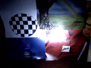 |
| 12/01/2002 22:06 | 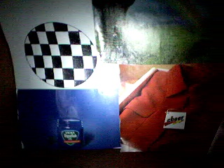 |
| 12/02/2002 18:15 | 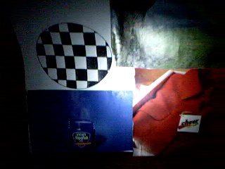 |
| 12/03/2002 18:05 | 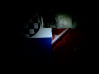 |
I have since discovered that even with fresh batteries, this is insufficient light for caving, mostly because it has no throw. I'm tempted to experiment with overdriving the LED's a bit, to see if this helps any at all.